Traveling Wave Tubes
Suppression of Intermodulation Products in a Broadband TWT
Suppression of intermodulation products is a crucial communications and ECM area. The suppression of nearest neighbor nonlinear products in a broadband TWT could allow one to fully utilize the bandwidth of a TWT for a variety of applications. We have focused on new techniques to accomplish intermodulation suppression and the underlying spectral evolution in our specially designed Northrup-Grumman research TWT.
A. Highlights of 2001-02 Research
- A TWT linearization technique using harmonic injection to suppress intermodulation products was investigated, obtaining a maximum IM3 suppression of 24 dB under optimum conditions. A research brief [1] containing the results has been published.
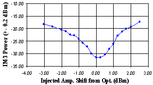
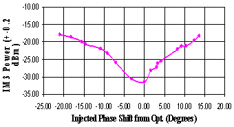
- Injected Amplitude and Phase sensitivity of the scheme was studied. It was found that IM3 power goes up by 3 dB for 0.5 dB change in amplitude or about 3 degrees change in phase of the injected harmonic.
- Further investigations involved observing the spatial evolution of the IM3 suppression. It was found that a particular amplitude and phase of the injected harmonic is needed to cancel the IM3 at a particular axial position.
B. Intermodulation suppression technique using Harmonic Injection
Traveling Wave Tube (TWT) amplifiers are used for their high power output but the non-linear behavior of these tubes leads to intermodulation interference when closely spaced multiple tones are amplified. The suppression of these intermodulation products is a crucial research topic for communication as well as ECM applications.
Growth of non-linear distortion products along the helix of the tube is measured using XWING, a custom-modified research tube jointly developed by UW and Northup-Grumman researchers that has sensors along the helix.

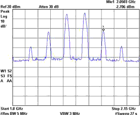
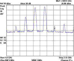
A linearization scheme was investigated where the harmonic (4.00 GHz) of one of the tones was injected along with the two fundamental tones (2.00 and 1.95 GHz). Phase locking of the harmonic to the fundamental was achieved by sharing a 10 MHz reference signal.

The amplitude and phase of the injected harmonic were adjusted by repeated iterations to achieve a maximum suppression of 24 dB for the upper IM3 [1]. The lower IM3 can be similarly suppressed by injecting harmonic of the other tone.


Amplitude and Phase sensitivity plots of IM3 suppression were obtained by varying the phase and amplitude of the injected harmonic and observing the IM3 level. It was found that IM3 power goes up by 3 dB for 0.5 dB change in amplitude or about 3 degrees change in phase of the injected harmonic.


Using the XWING, spatial evolution of the suppression mechanism was studied using the sensors along the helix. It was observed that a particular value of injected harmonic amplitude and phase is needed to achieve maximum suppression of the IM3 at a particular axial position. The required level of the injected harmonic was found to be very small compared to the fundamental level. For the optimum case, an IM3 reduction of 24.2 dB was observed for an injected harmonic drive level of only 0.9 dBm, or 17.1 dB below f2.
The spatial spectrum shown in Fig. 5 indicates that the upper IM3 (2f2-f1) initially grows from sensor 1 to sensor 4. When the IM3 due to beating of the injected harmonic (2f2) with the other fundamental (f1) becomes strong enough in amplitude with an opposing phase, the resultant IM3 starts to decay and is a minimum of 46 dBc at the output of the tube.

C. Current/Future objectives:
- The initial set-up needed Phase-locking of the harmonic synthesizer to the fundamental using a 10 MHz reference. Phase stability issues were found to be critical and a frequency doubler set-up is being explored.
- Investigations are underway to obtain a more complete spectrum (including IM5s and harmonics) in an attempt to understand and analyze the scheme more thoroughly.
- It is also of interest to find out the bandwidth or the effective frequency range over which suppression would be effective using the harmonic injection technique. It is planned to vary f1 and observe the effect on suppression.
- To overcome the phase sensitivity of harmonic injection, another technique is proposed that will involve injecting two frequencies and varying only their amplitudes to cancel an intermodulation product. The idea is to remove the sensitivity on injected phase by canceling the unwanted component in amplitude and phase using two amplitudes as control variables, while the phases will need to satisfy only a polarity condition.
- AM-AM and AM-PM measurements: Currently, we are characterizing the traveling wave tube amplifier using AM-AM (P-out vs. P-in) and AM-PM (delta-phi-out vs. P-in) curves. The output of the tube is mixed down to a 20 MHz frequency so that real-time data can be monitored. This would enable to account for any changes in gain and phase due to the slight droop that is present on the cathode voltage pulse. This information is lost when a spectrum analyzer is used to look at the TWT output.
Relevant Publications
- M. Wirth, A. Singh, J. E. Scharer and J. Booske, “Third – Order Intermodulation Reduction by Harmonic Injection in a TWT Amplifier,” IEEE Trans. on Electron Devices, pp. 1082, vol. 49, 2002.
- A. Singh, J. E. Scharer, J. Booske, and J. Wohlbier, “Second- and Third-Order Signal Predistortion for Nonlinear Distortion Suppression in a TWT,” IEEE Transactions on Electron Devices, May 2005.
- A. Singh, J. Wohlbier, J. Booske, and J. E. Scharer, “Experimental verification of the mechanisms for nonlinear harmonic growth and suppression by harmonic injection in a traveling wave tube,” Physical Review Letters, May 2004.
